
Hi, I’m Tam

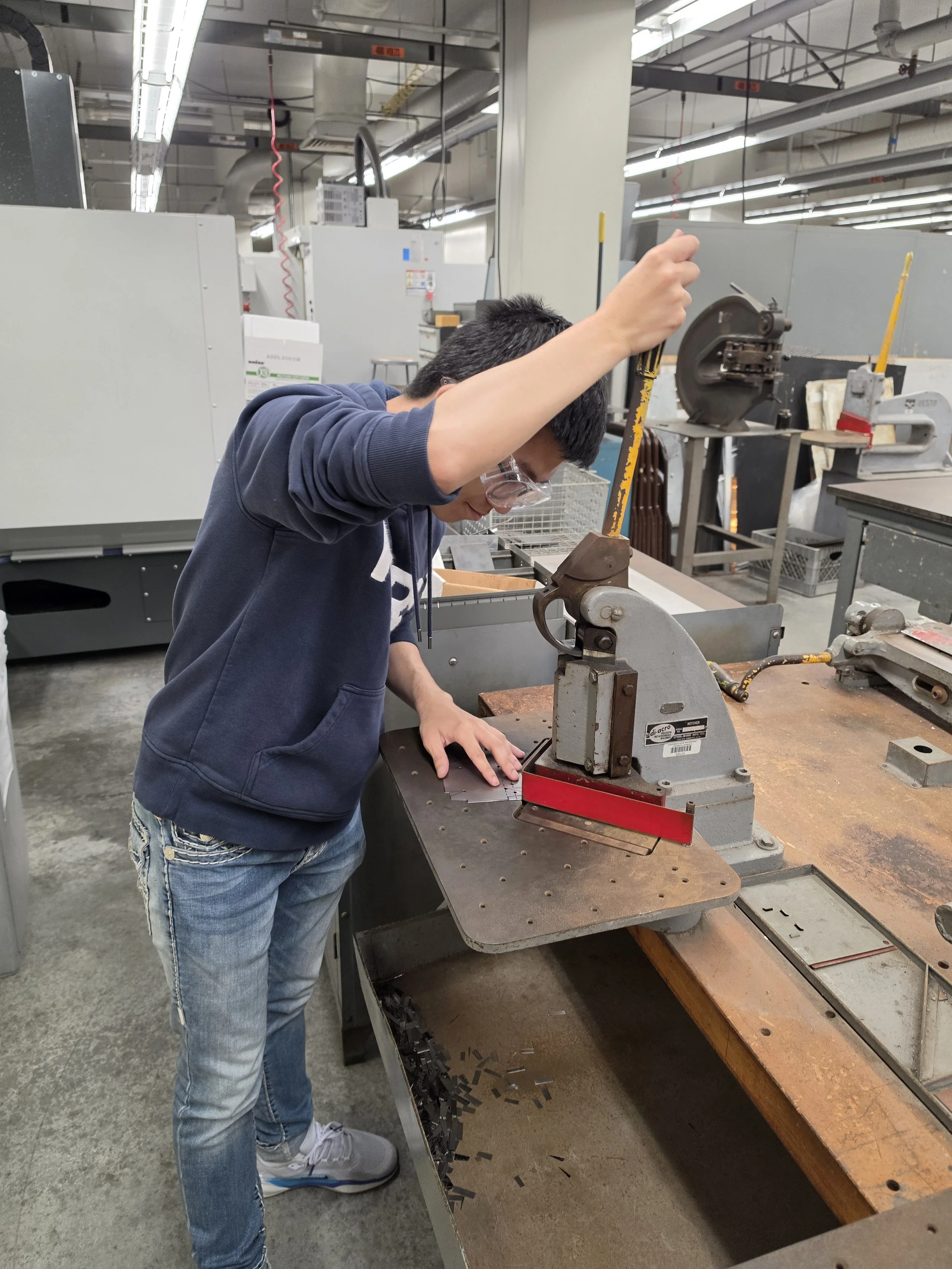
I am an Electromechanical Systems Engineering Technology student at Cal Poly Pomona. I currently work as a Research Assistant and an Engineering Tutor in the College of Engineering department. I enjoy hands-on engineering, especially 3D modeling, prototyping, and testing electro-mechanical systems.
Line-Following Robot
Line-Following Robot
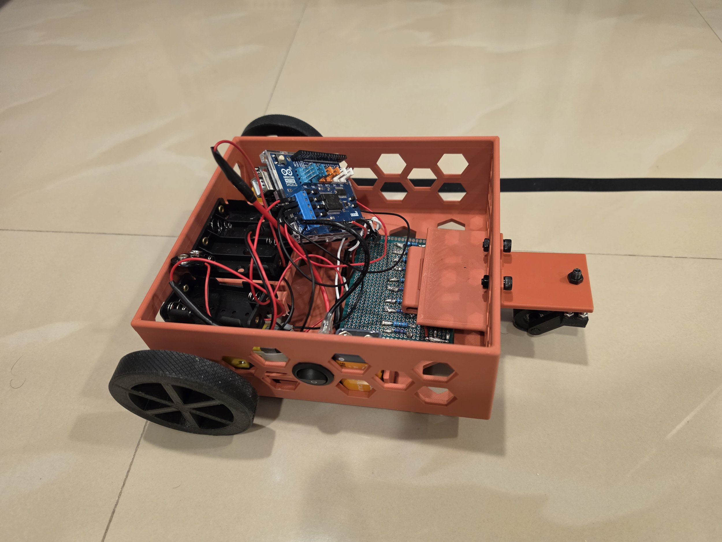
Developed a cost-effective line-following robot that is capable of accurately tracking complex paths using a simple and efficient design. Emphasized reliability and performance while minimizing component cost and system complexity. The robot uses IR LEDs and phototransistors sensors as its “eyes” to see and move along a black line.
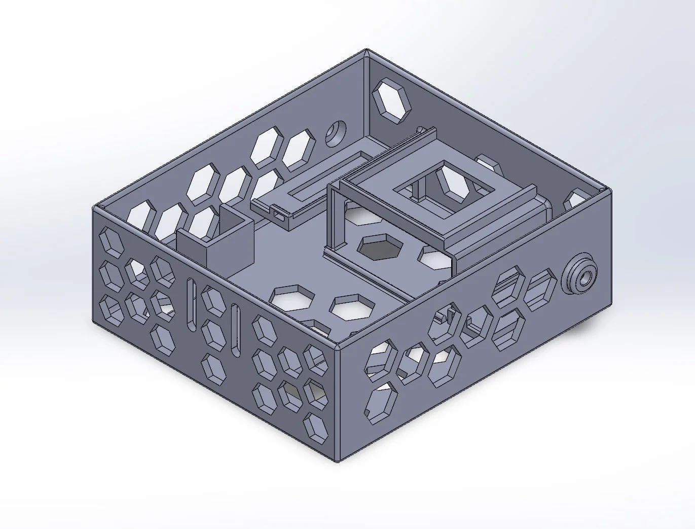
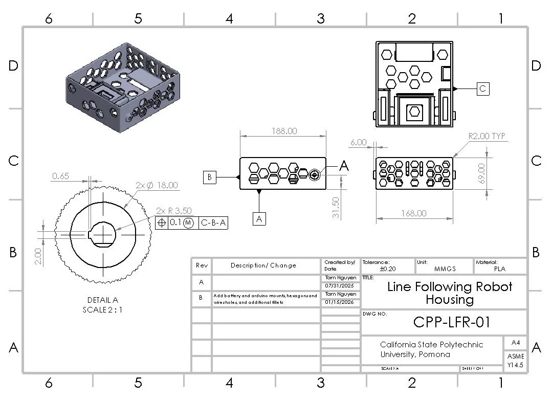
Designed & Manufacturing
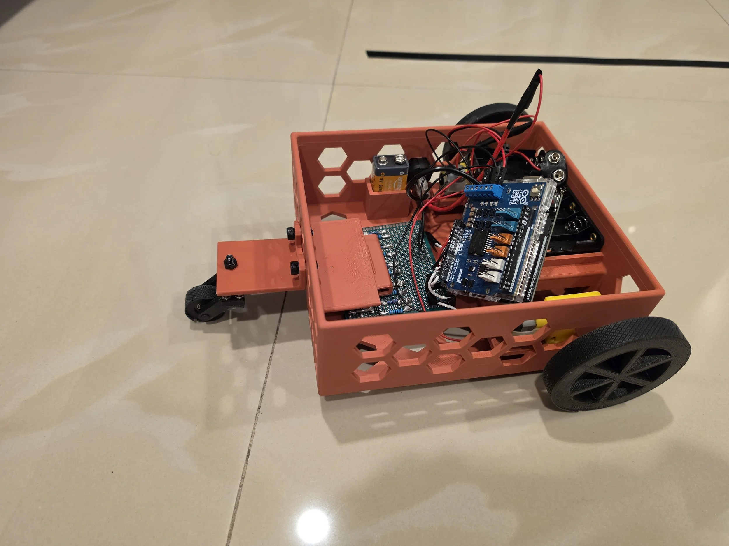
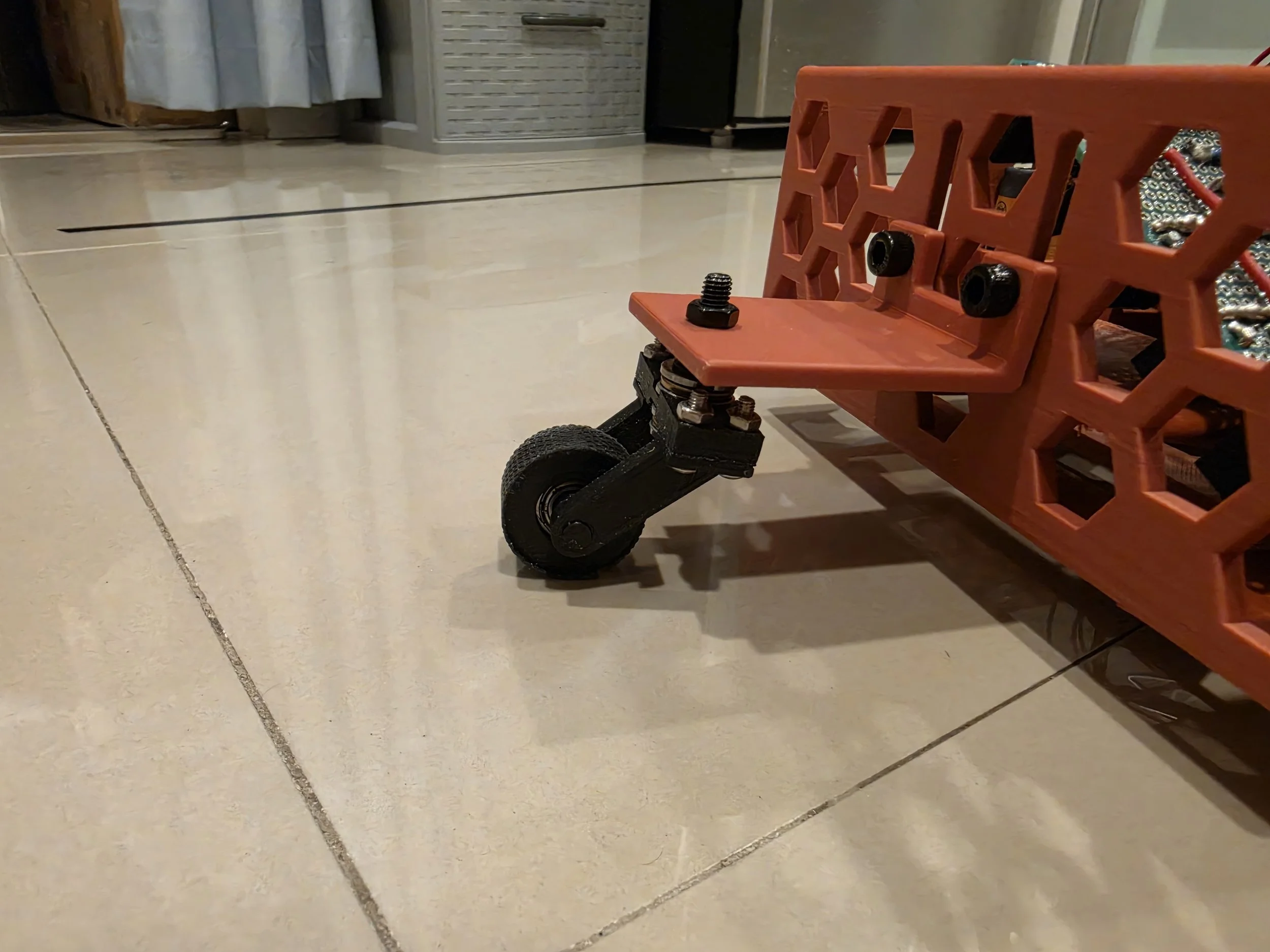
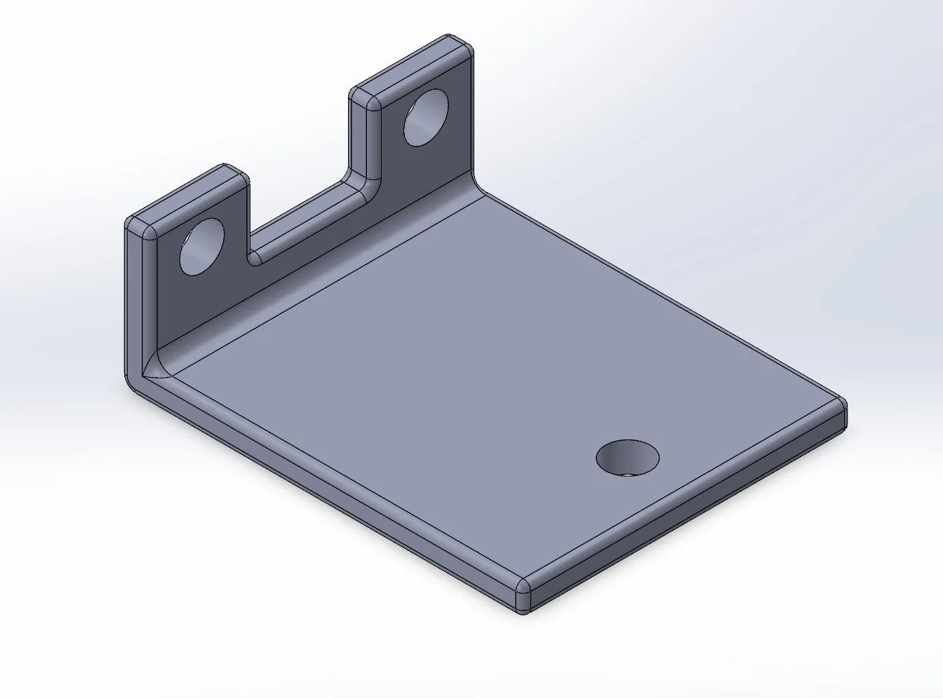
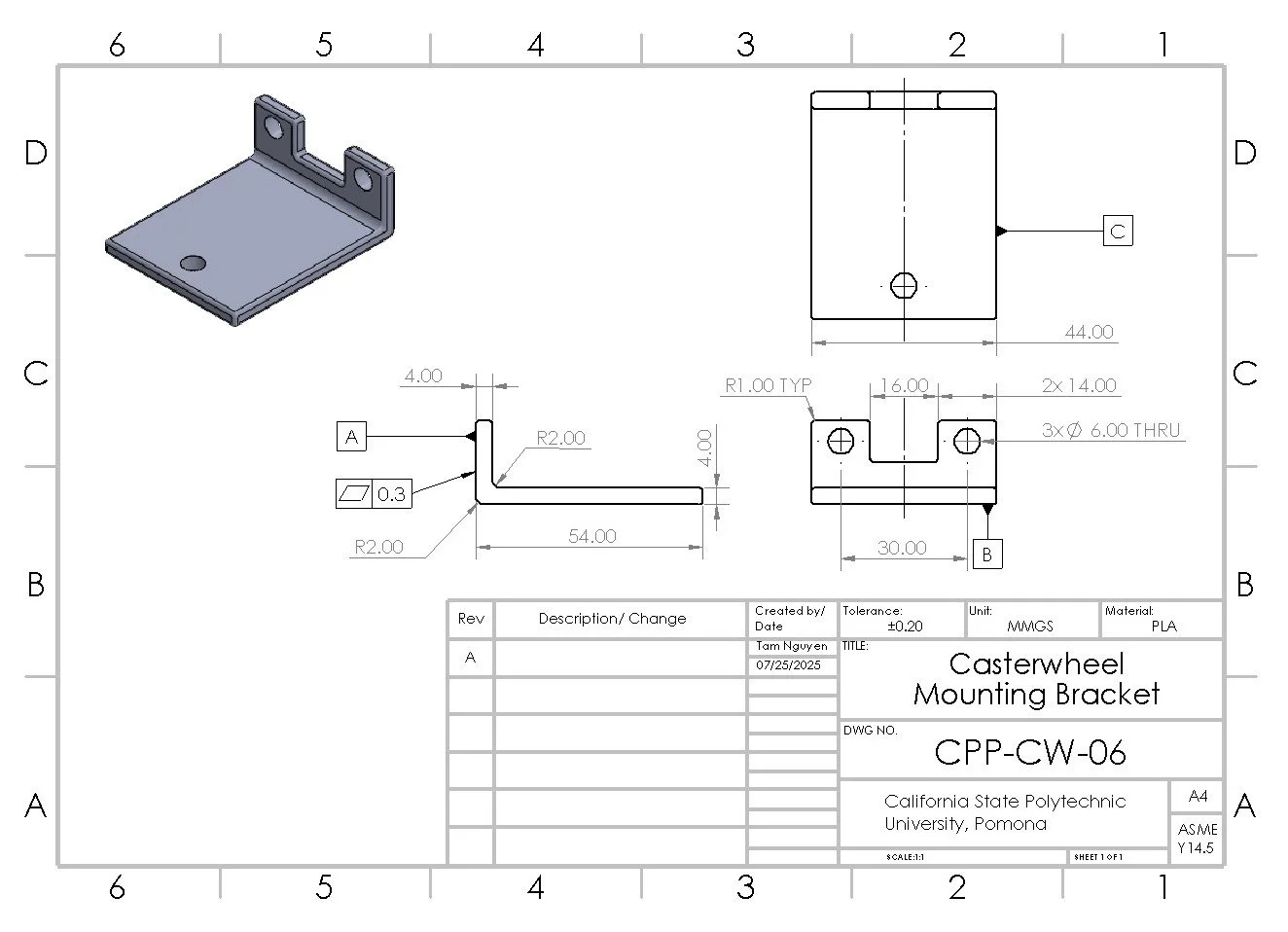
I designed and modeled the Line-Following Robot’s parts, including the frame, wheels, mounts, and caster wheel, using SolidWorks. The parts were then fabricated via 3D printing using PLA.
Cont.
Electrical Systems & Sensors
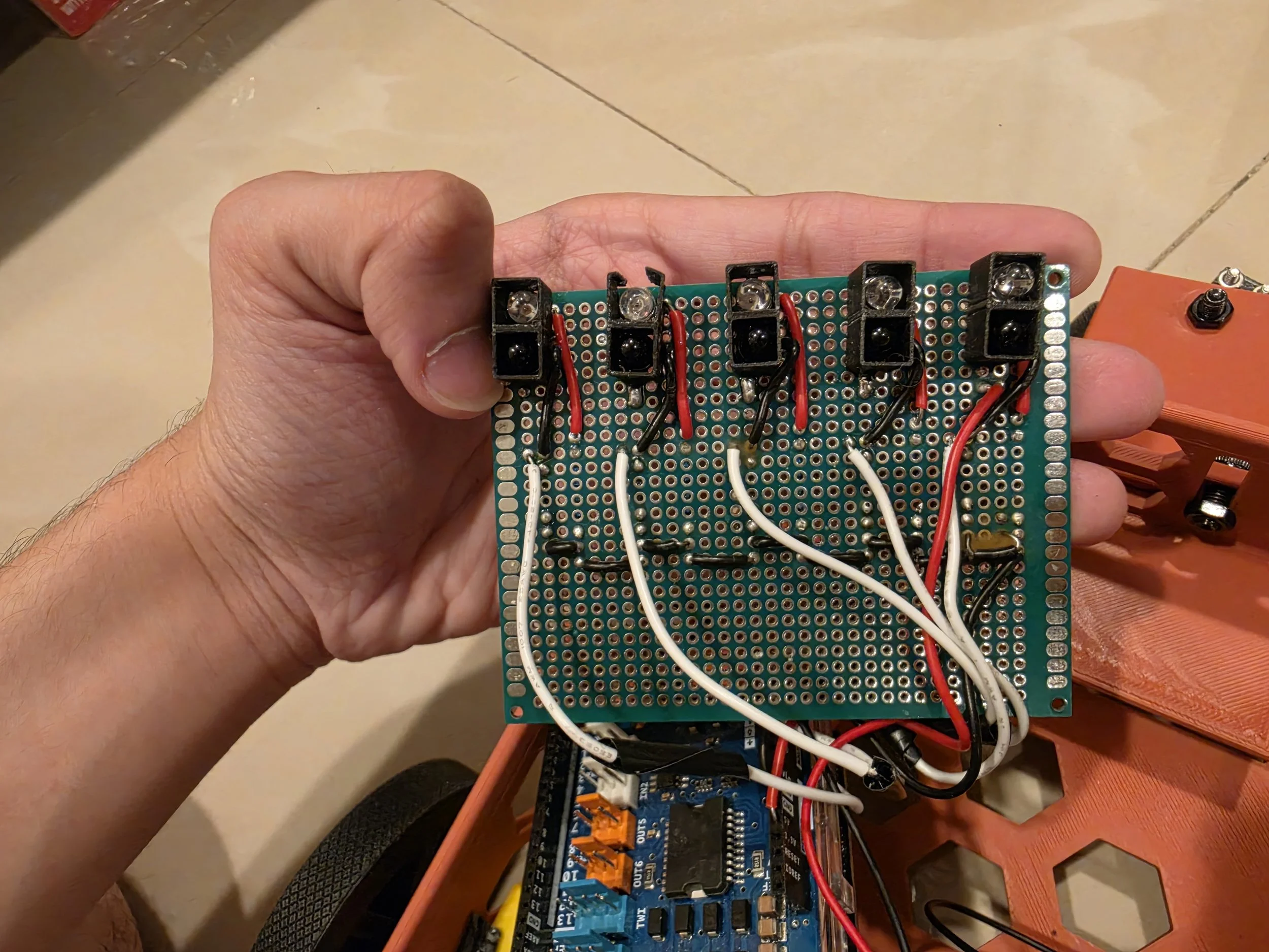
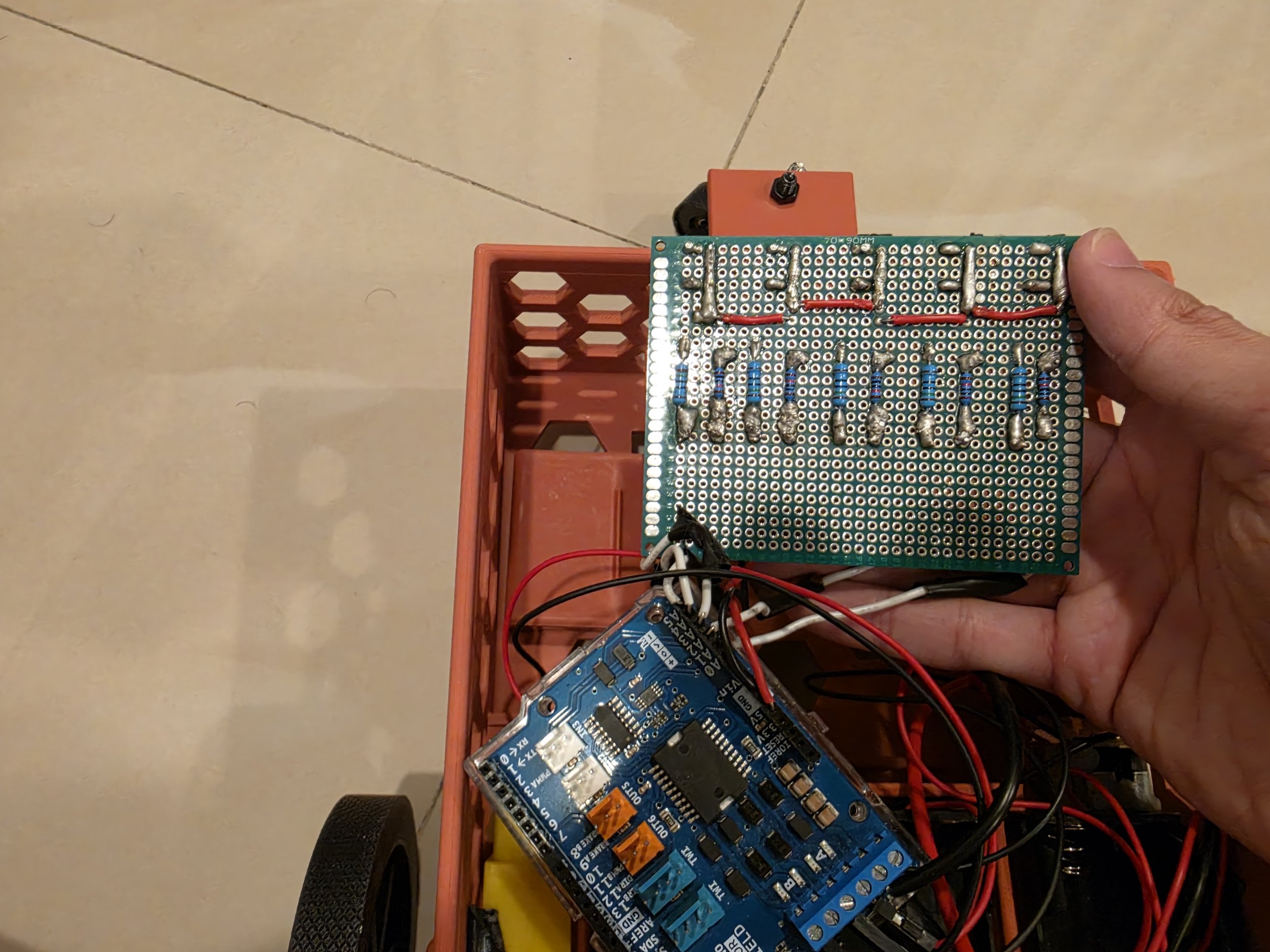
Soldered resistors, IR LEDs, phototransistors, and wiring onto a perfboard to build the circuit, ensuring solid and reliable connections. The system was then integrated with an Arduino MEGA 2560 and the Arduino Motor Shield (L298) to control the two motors. The robot will run until all of its sensors (the black phototransistor) no longer receive any IR light from the IR LEDs (the white LEDs).
Programming
I developed the control program for the line-following robot using Arduino IDE, consisting of approximately 130+ lines of code. The system was tuned through multiple iterations over several days to achieve stable and accurate path tracking.
One of the main challenges was the limited performance of the IR sensors, which produced a narrow output range (approximately 0–20) compared to the typical analog 0–1023 output range. This made the robot become difficult to follow the path correctly and required careful calibration, threshold tuning, and repeated testing to achieve reliable behavior.
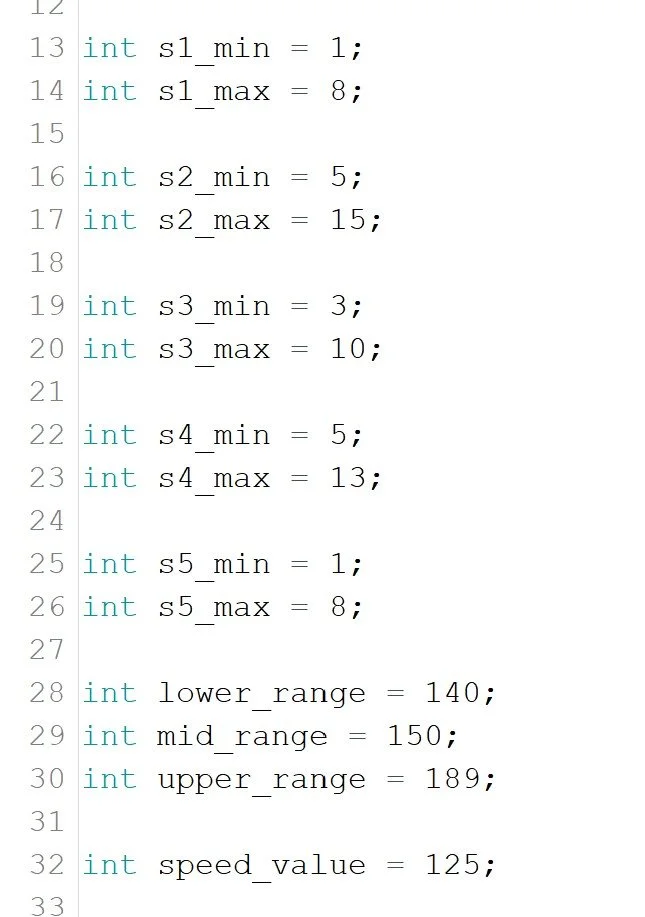
Lines 13-32: The parameters that need to be adjusted repeatedly after each testing
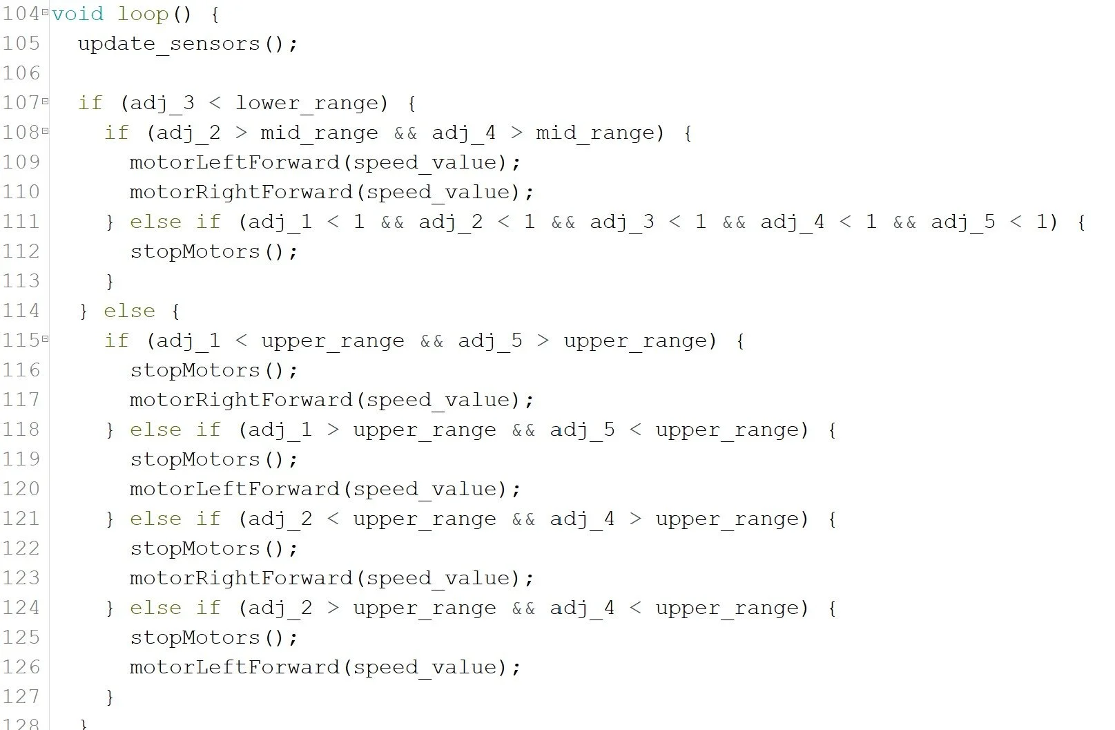
Lines 104–126: The Arduino uses parameters defined in lines 13–32 and the output from the sensors to perform logical operations and determine the robot’s direction, such as which motor (or both) should move or stop
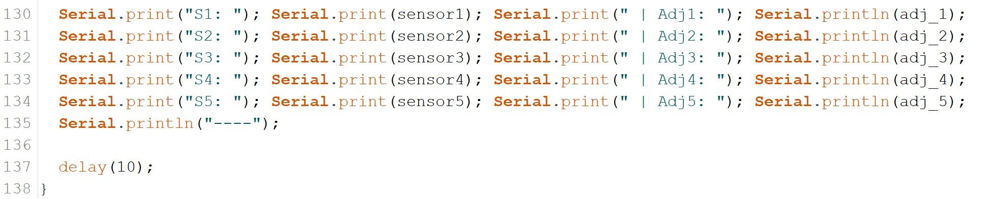
Lines 130-138: The final lines will show how the robot is responding to its environment so that I can adjust the sensors parameters to match the output from the sensors range (min/max values) and the determine if the robot is adjusting to the correct direction or not.
Final Demonstration
This demonstration shows the robot operating at its maximum speed without swaying too much. The current system is able to follow the path reliably, though there is still room for improvement, such as using higher quality sensors and stronger motor with better battery to enhance its speed, sensor sensitivity, and stability.
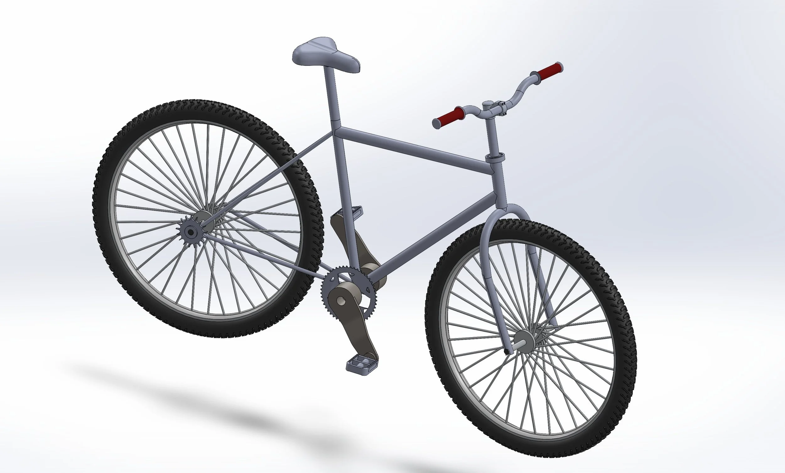
The Single-Speed Bicycle
The Single-Speed Bicycle
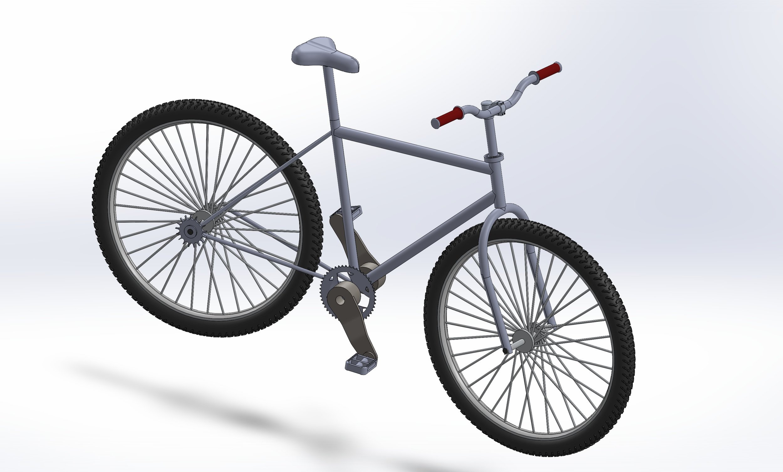
For this project, I led a team of 5 to develop a single-speed bicycle, a simple and efficient mechanical system that converts rider input into forward motion. The goal was to create a complete and functional design while emphasizing simplicity, reliability, and proper component integration.
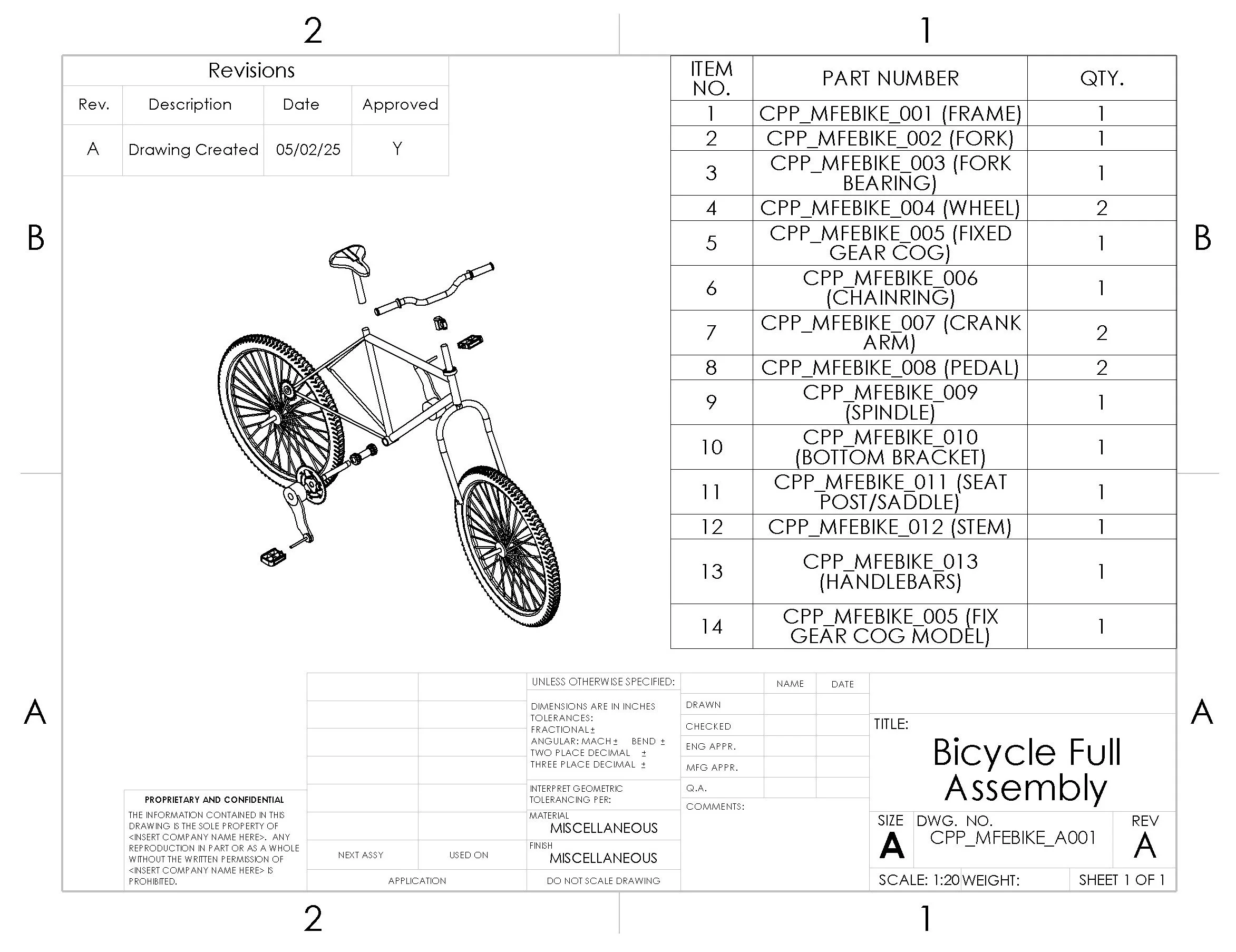
Part Models & Drawings
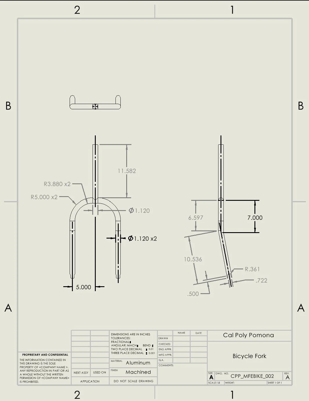
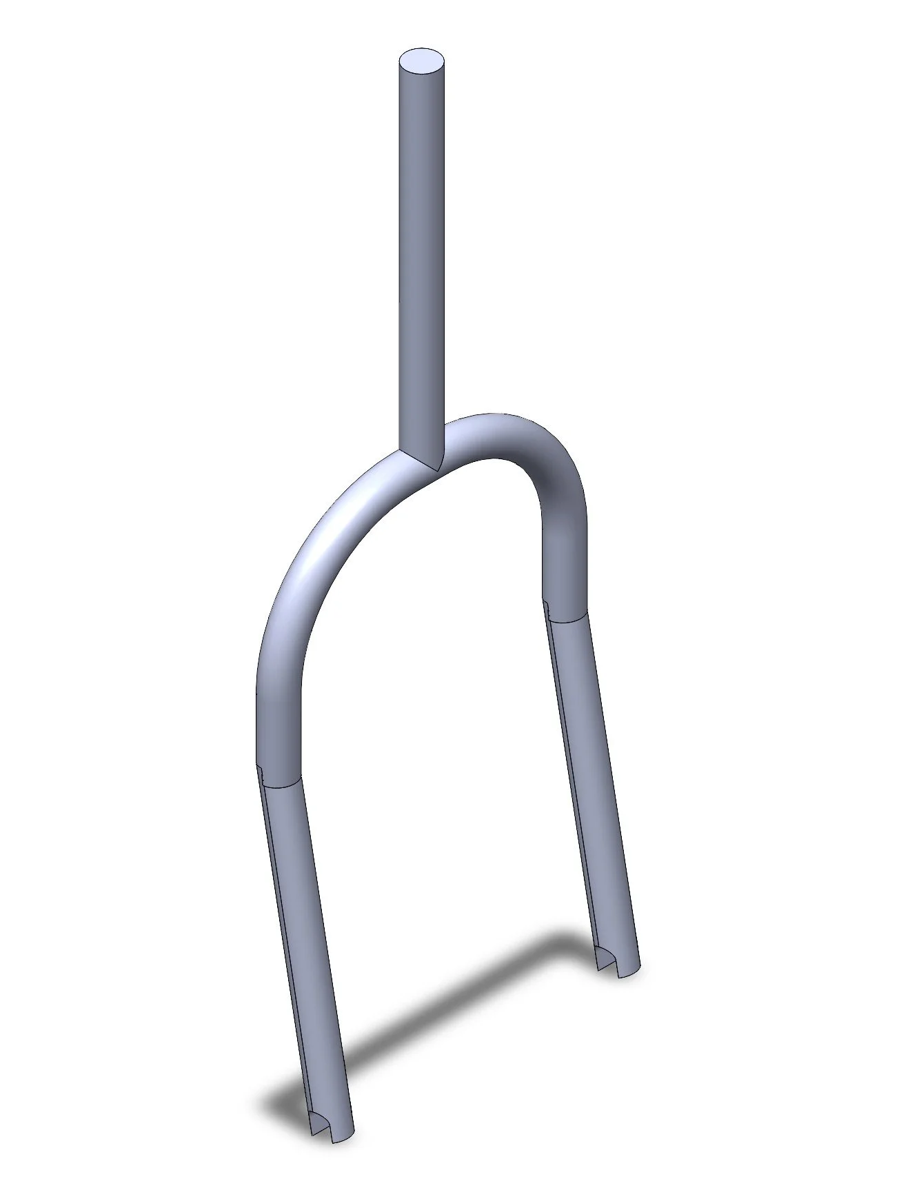
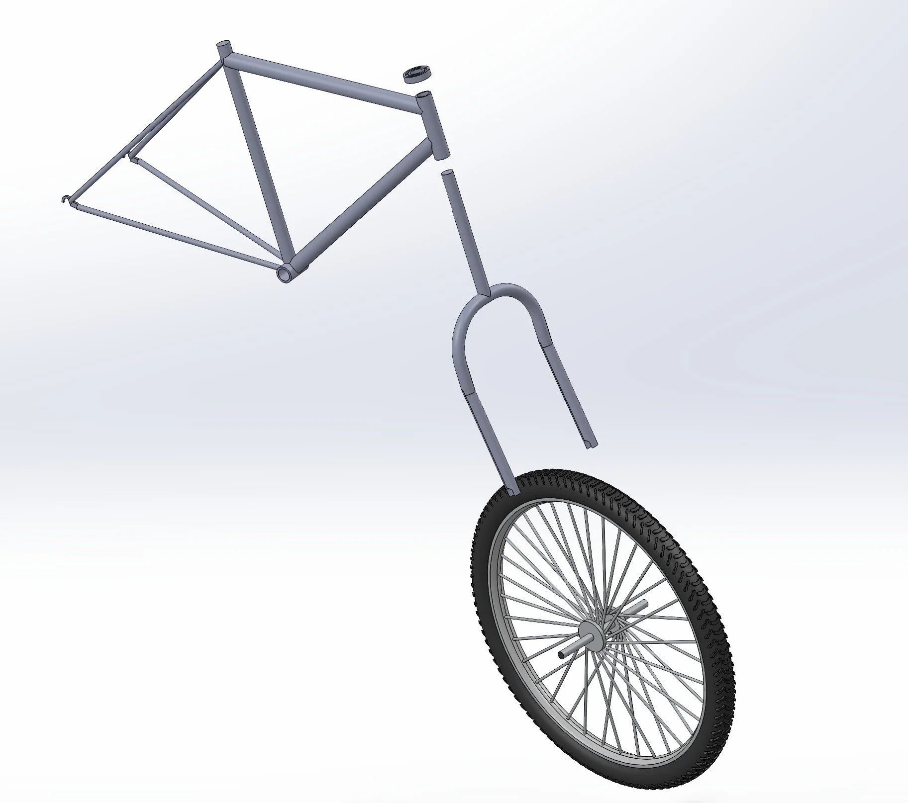
Fork
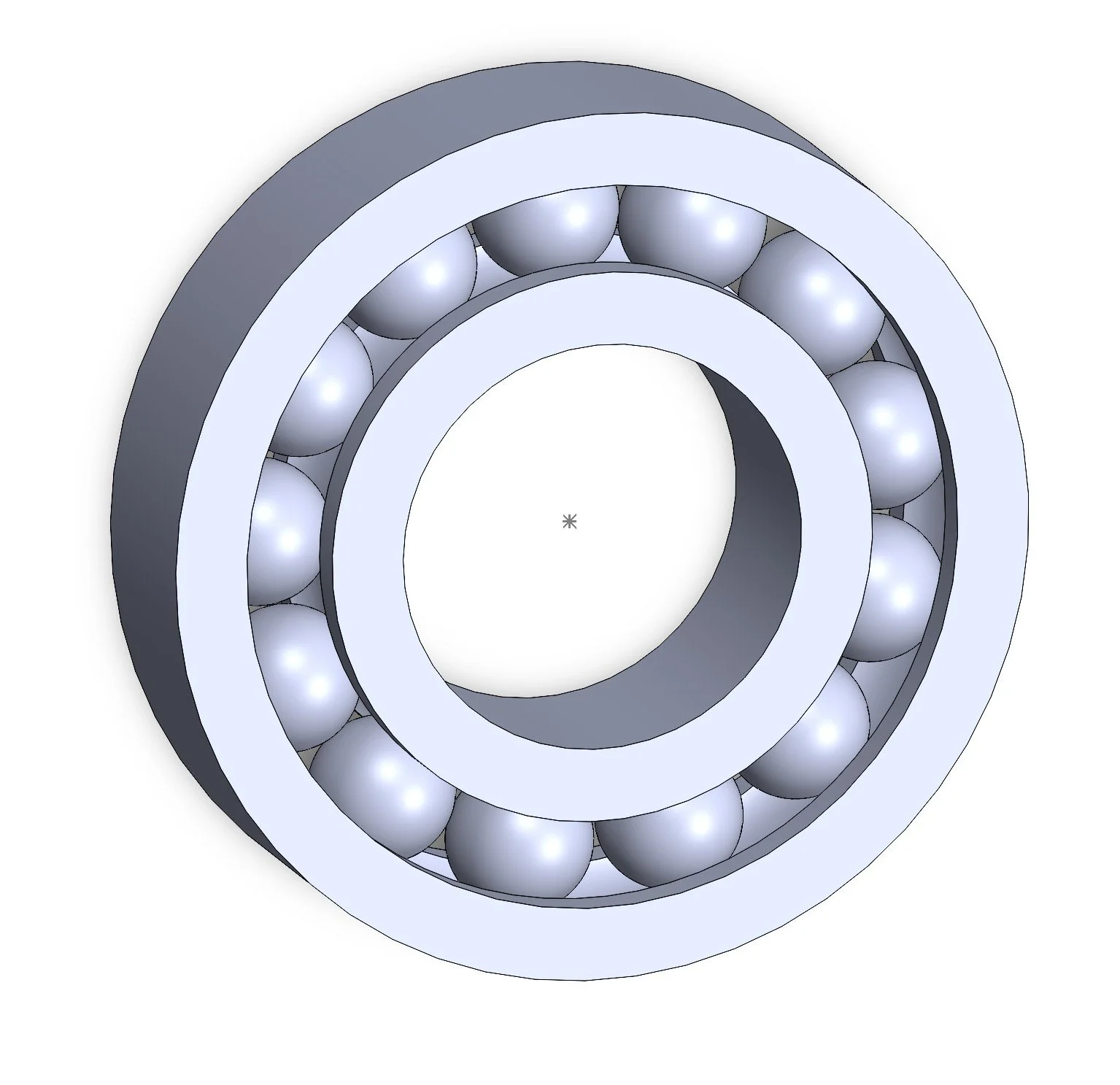
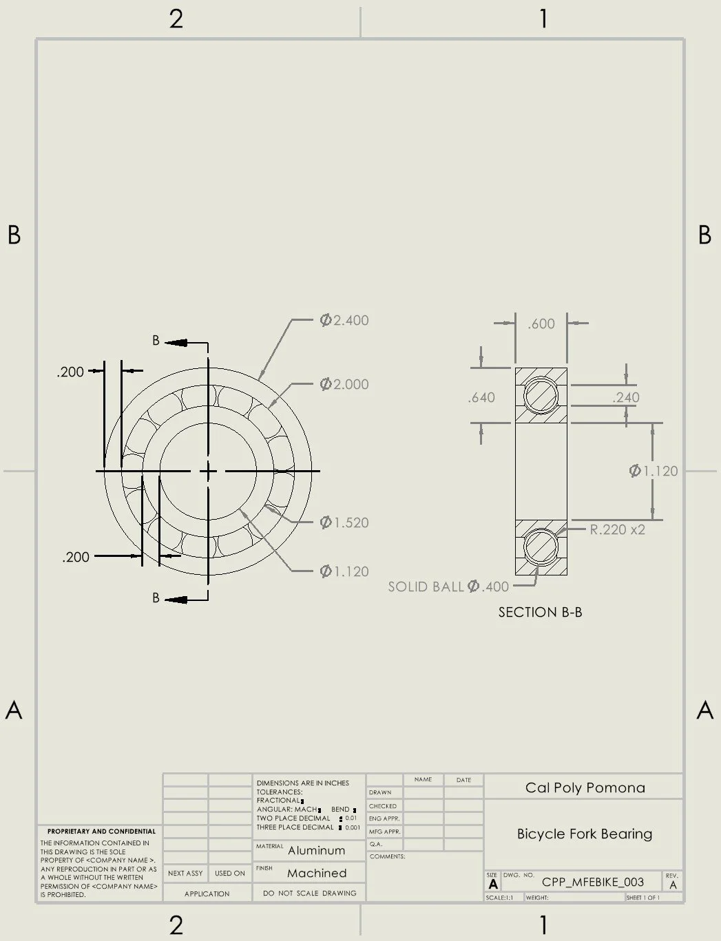
Ball Bearing
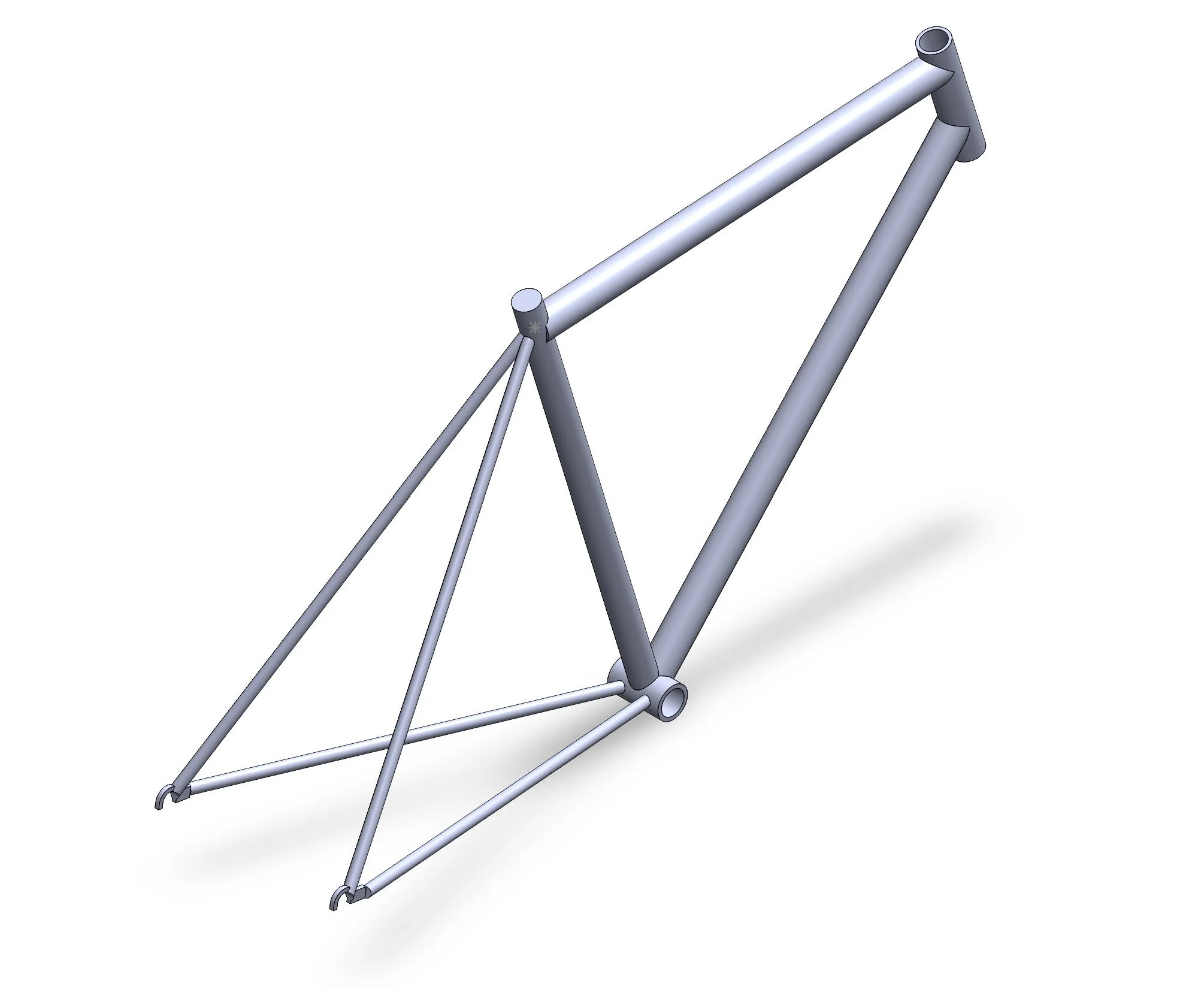
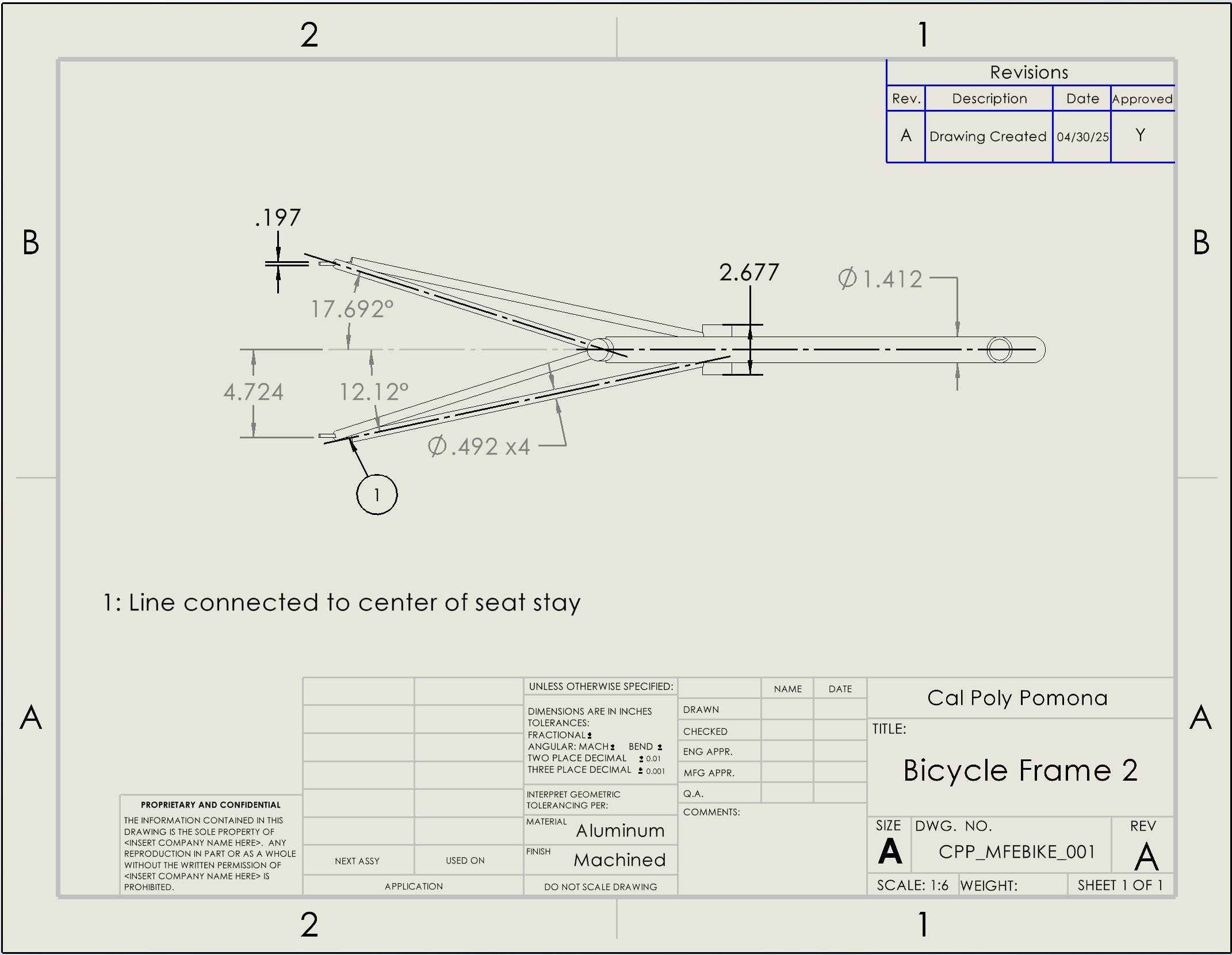
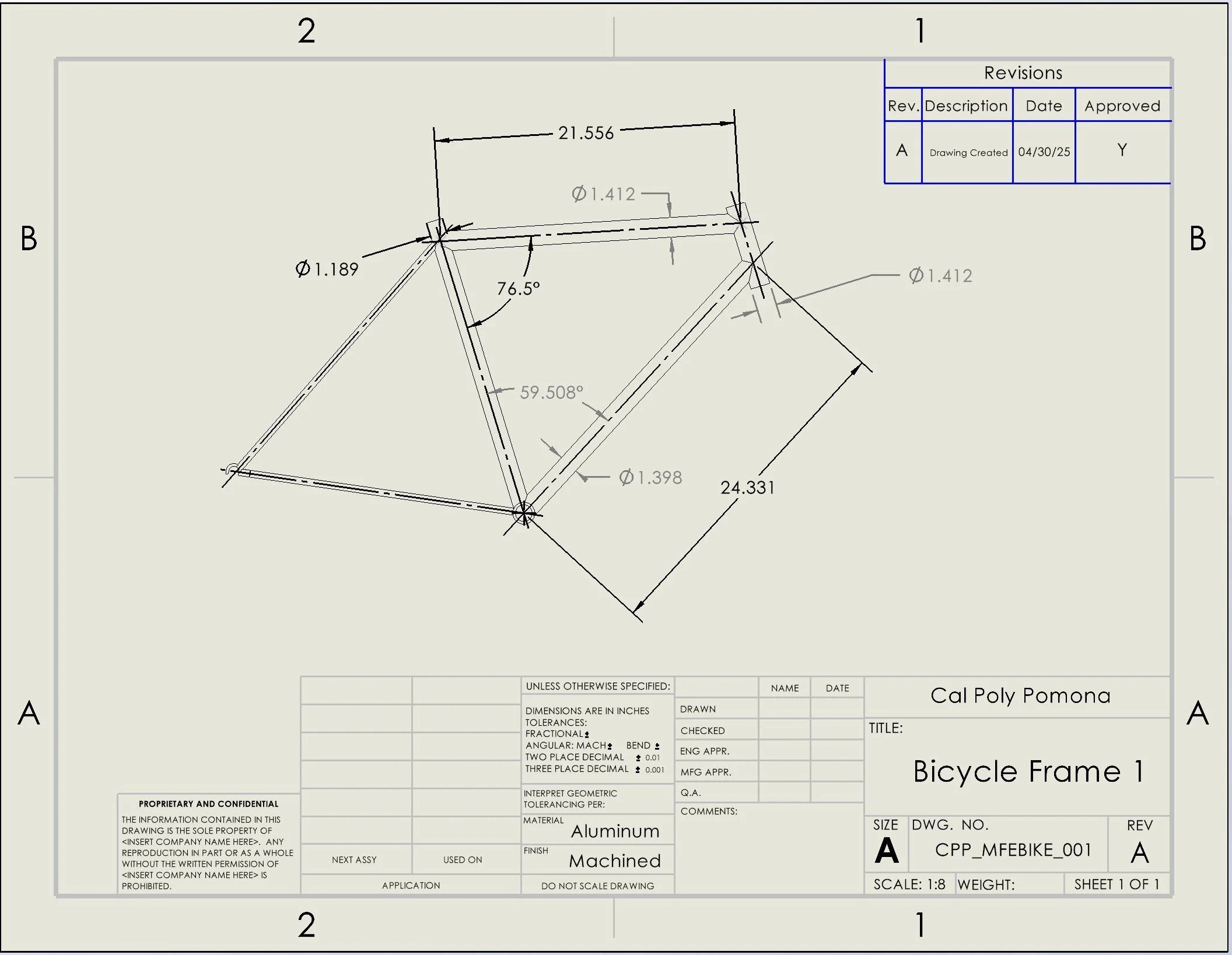
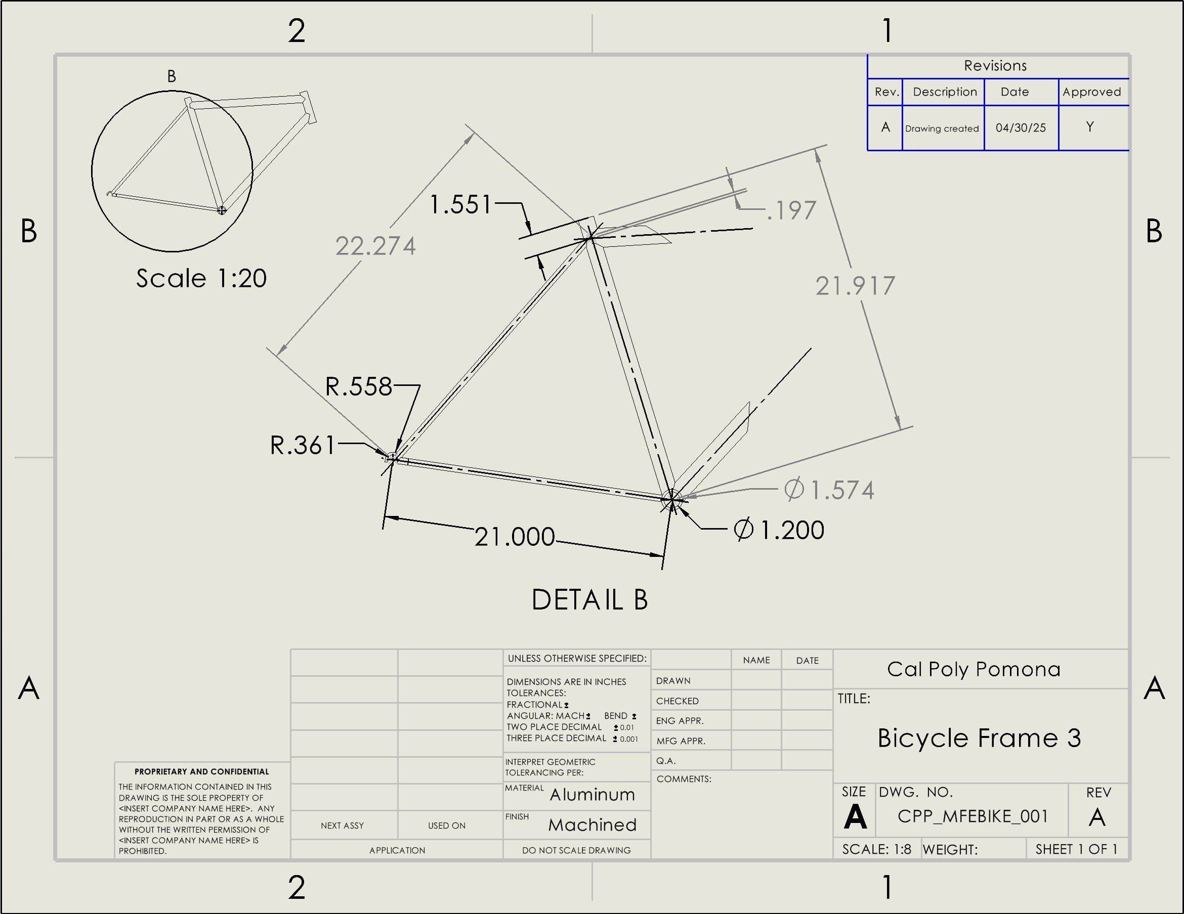
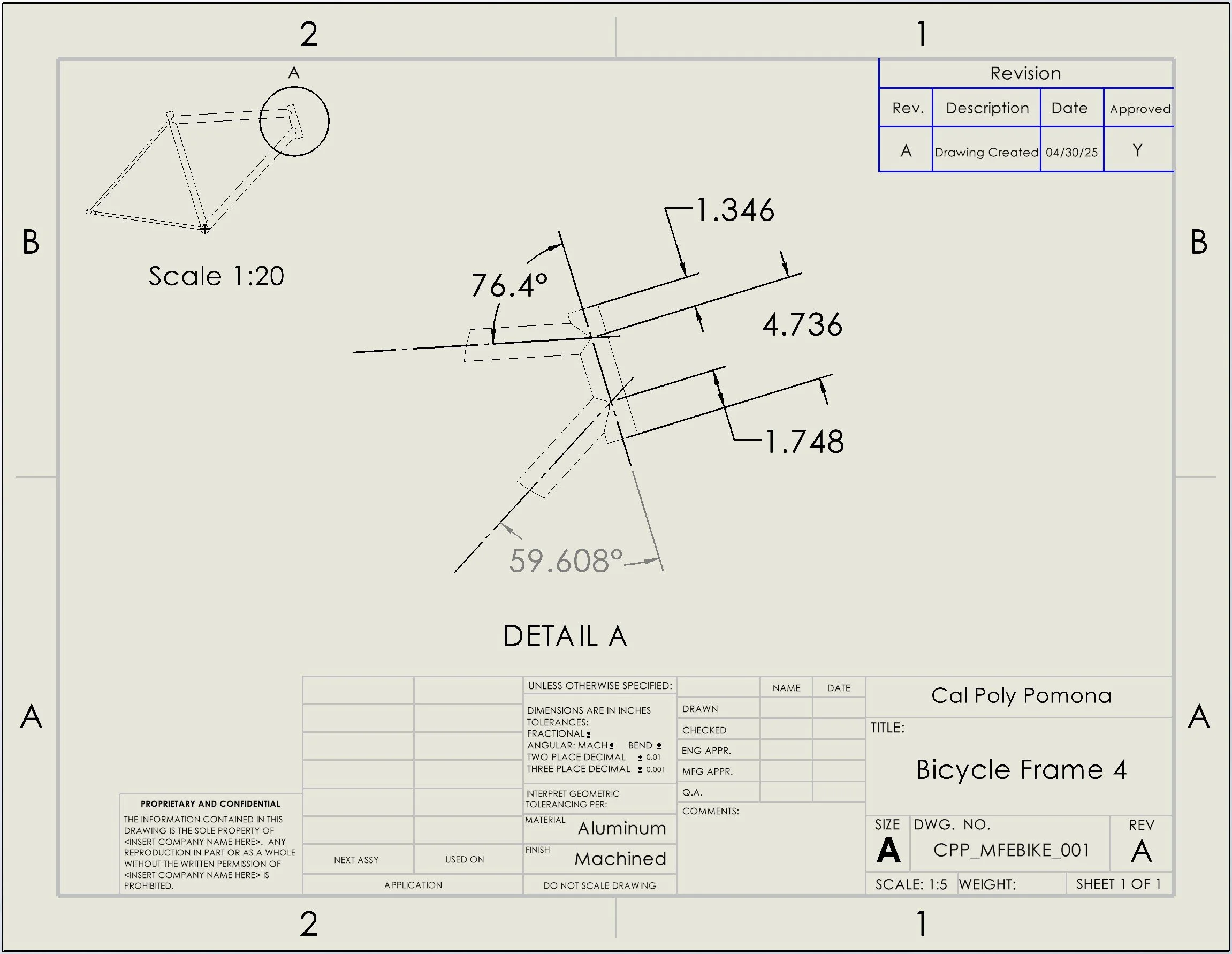
Bicycle Frame
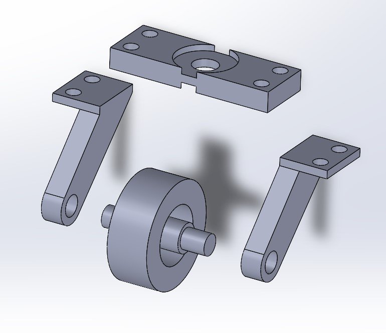
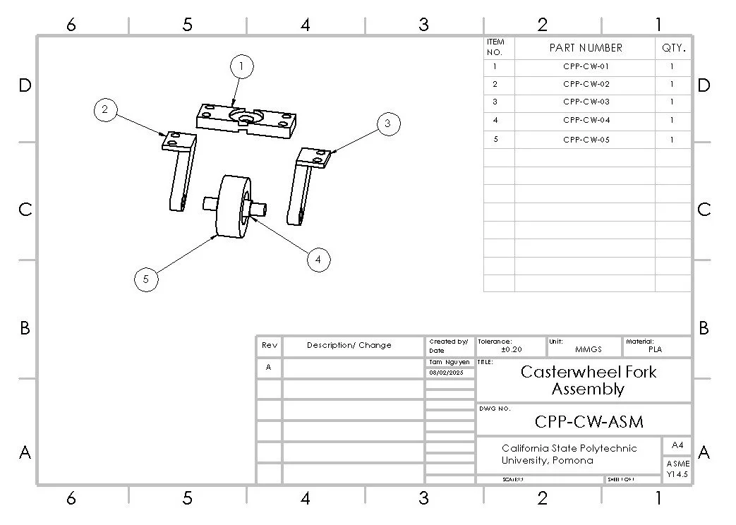
Assembly Models & Drawings
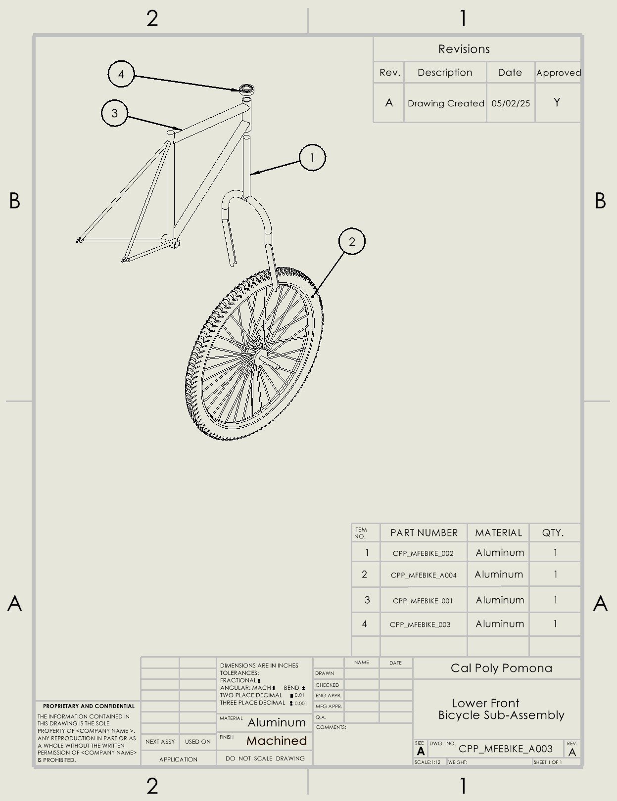
Lower Front Bicycle Sub-Assembly
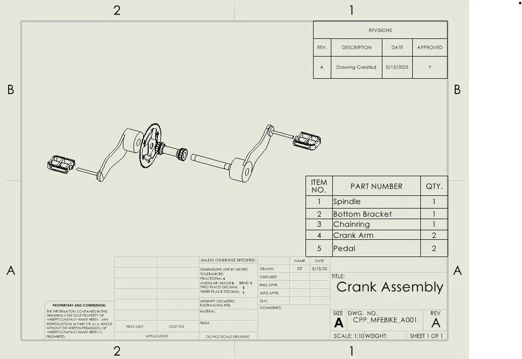
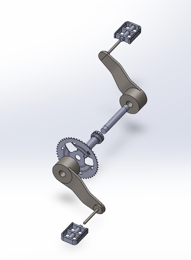
Crank Assembly

The Rolling Robot
The Rolling Robot (In Progress)
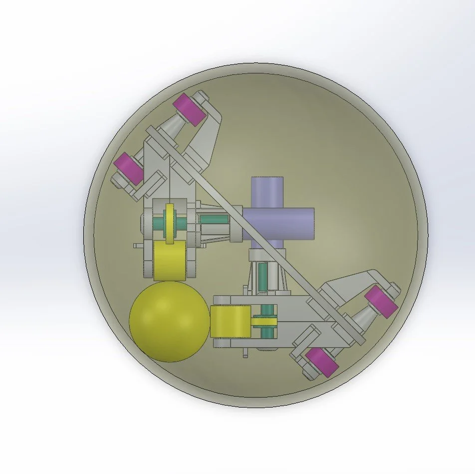
This project focuses on the design of a rolling robot that is capable of maintaining stable and controlled motion across various surface conditions through an internal gear-driven mechanism. The system utilizes a combination of spherical and custom gear profiles to enable controlled rolling and directional movement within a compact structure
The picture on the right shows the assembly of the Rolling Robot where the yellow parts are the spherical gear, monopole gear, drive gear, and the whole outer sphere is also a gear itself as well with gear-like internal geometry
Gear Designs
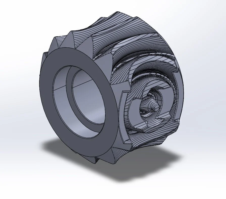
The gears showed here have the same tooth profile as traditional gears, however, their geometry are very different, and for a gear like the spherical gear and outer spherical gear, they can rotate in multiple direction. The pinion gears will be used to drive the monopole gears, and the monopole gears will drive the spherical gear. The spherical gear will drive the outer spherical gear, which is the housing that contains the robot.
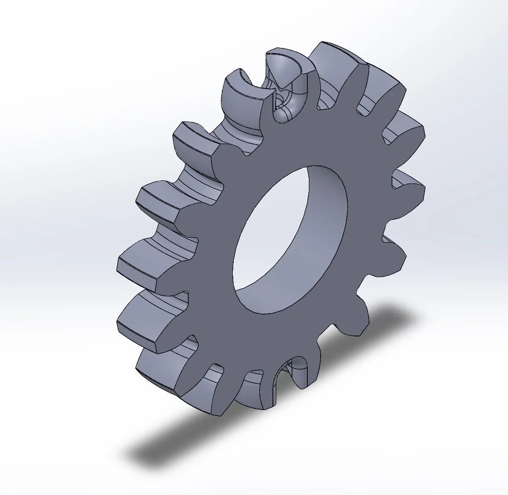
Pinion Gear
Monopole Gear
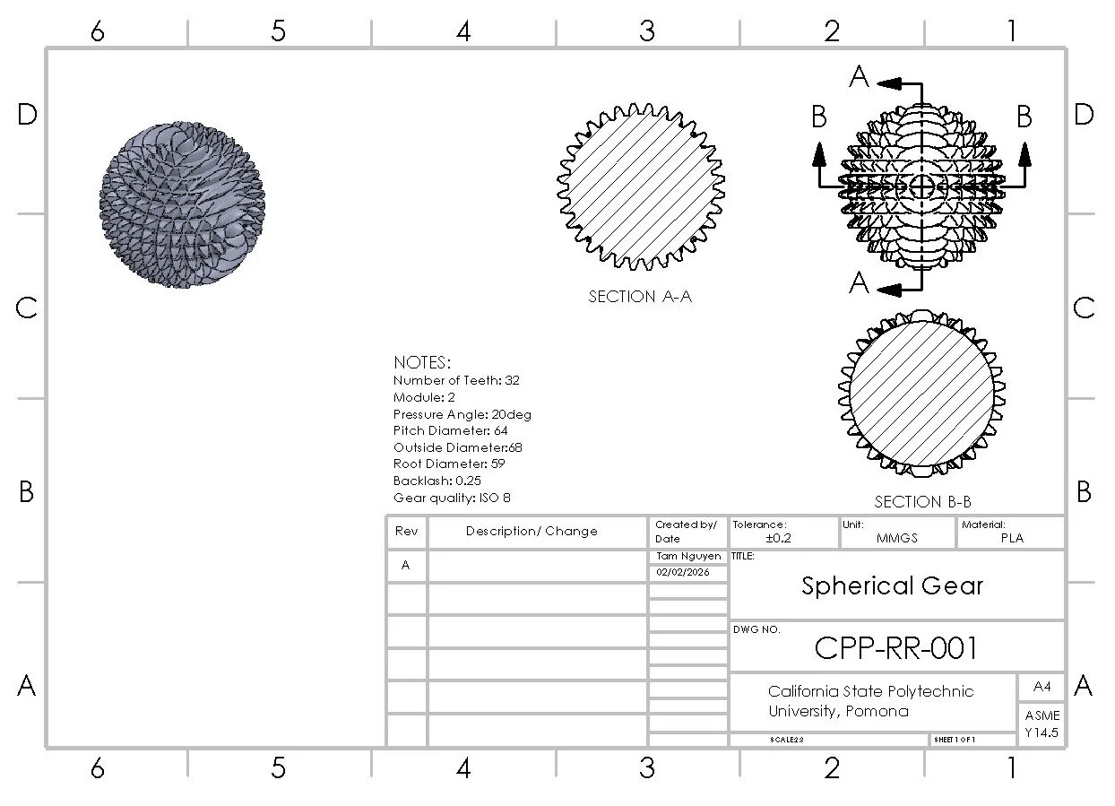
Spherical Gear
Robot Housing Design & Testing
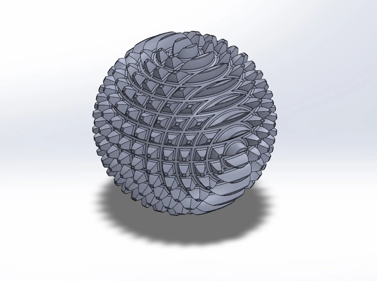
The spherical gear will be used to drive the outer spherical gear which is also the housing that contain the whole robot inside.
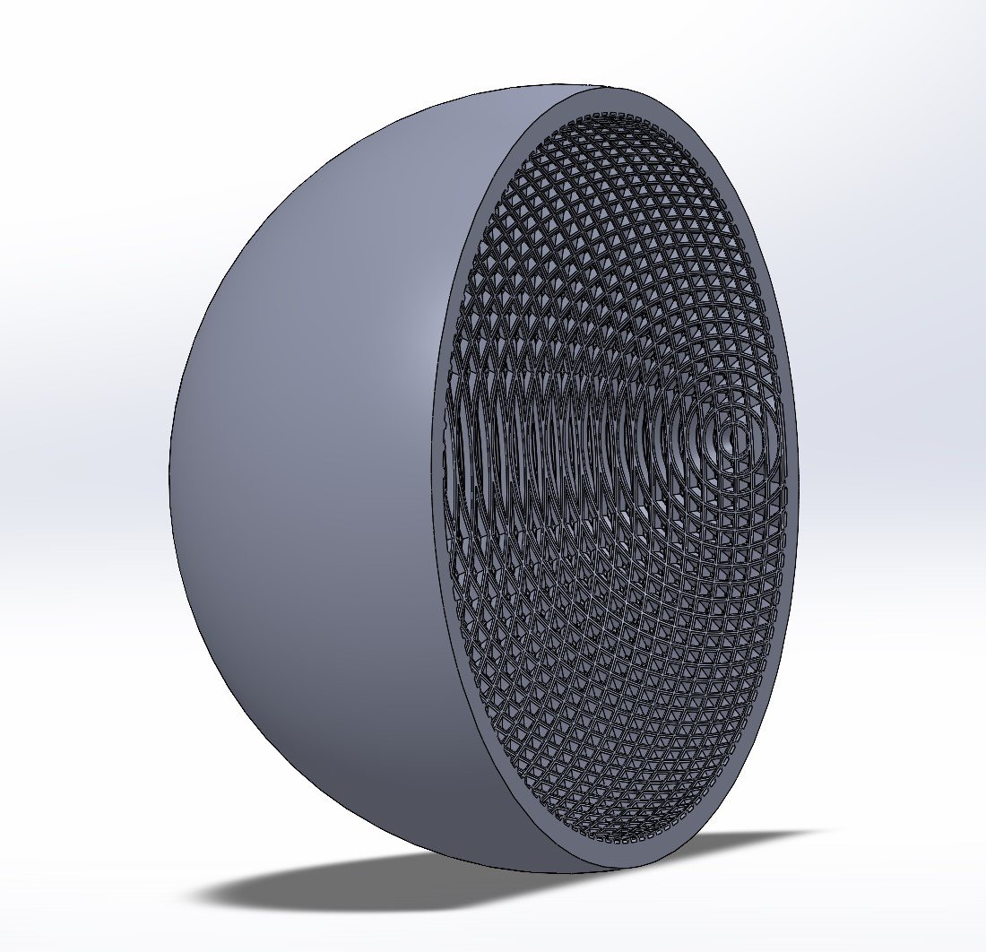
Outer Spherical Gear
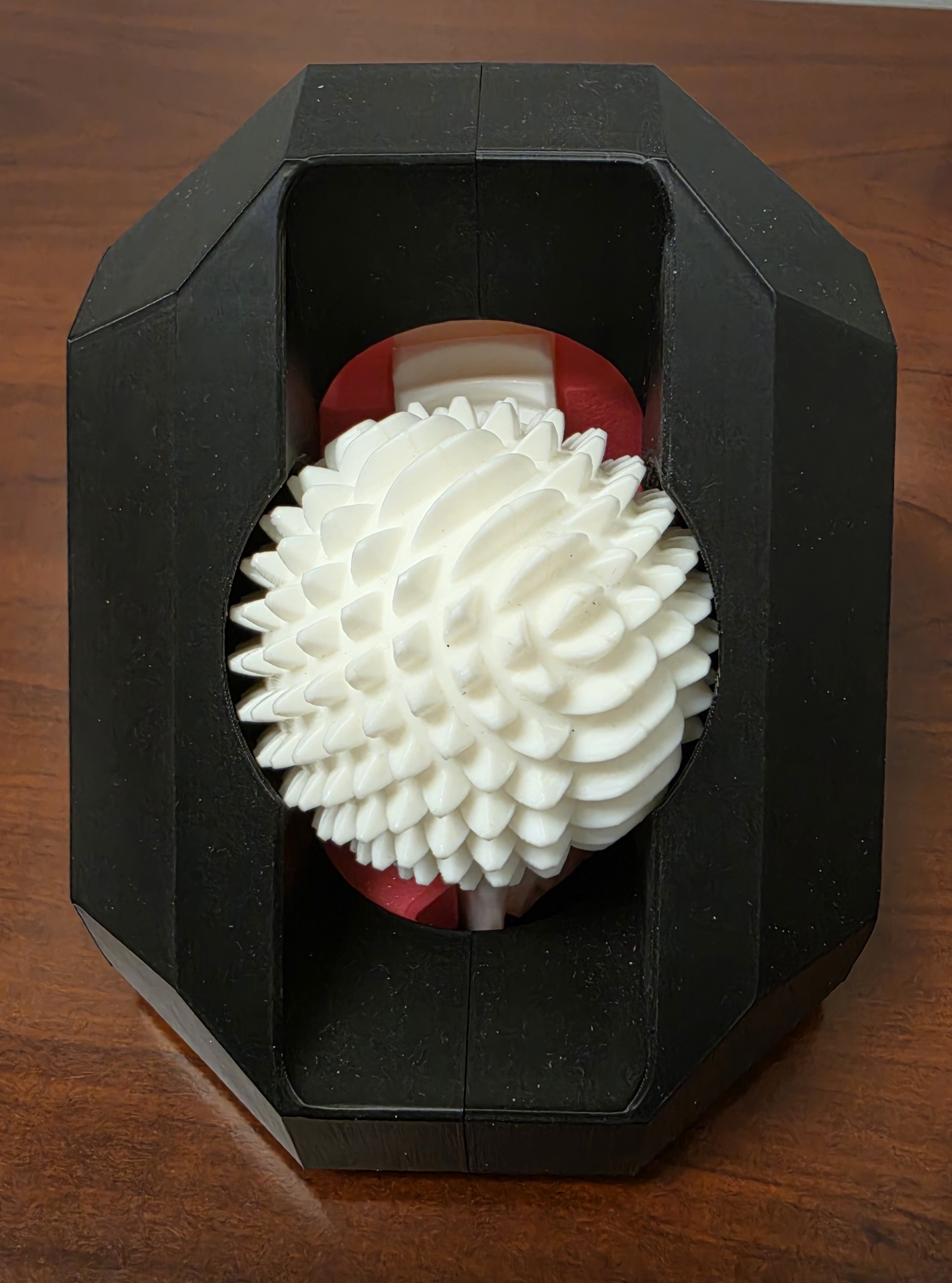
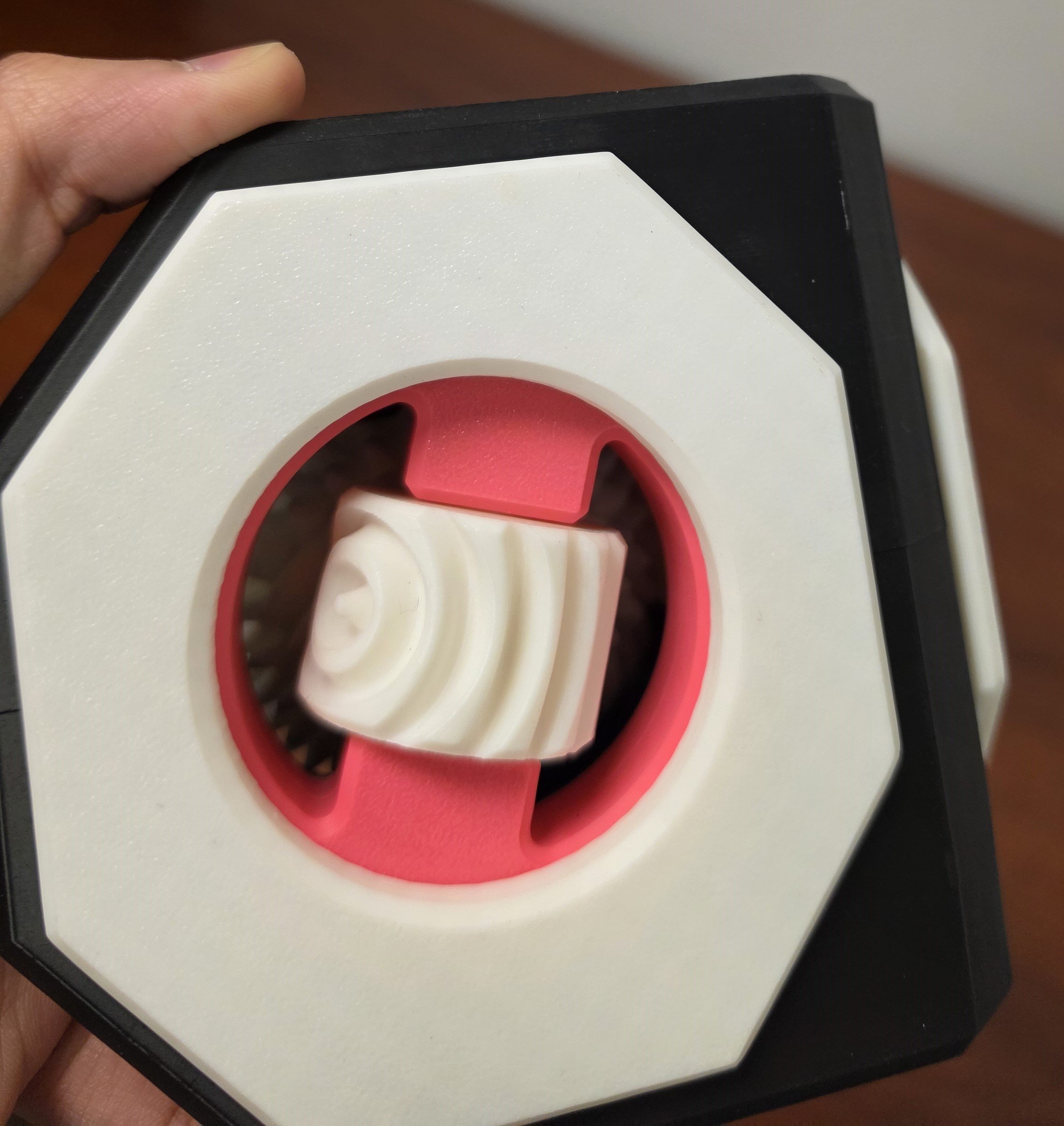
By using a custom housing, I am able to test the spherical gear (left picture) and the two monopole gears on each side (right picture) to see whether they can mesh correctly or not.
ANSYS Fluent Analysis for T-Pipe
Conducted a CFD analysis of water flow through a T-joint pipe under typical household conditions using ANSYS Fluent. I extracted the volume of the pipe, then analyzed its velocity distribution, pressure behavior, and regions of high shear stress.
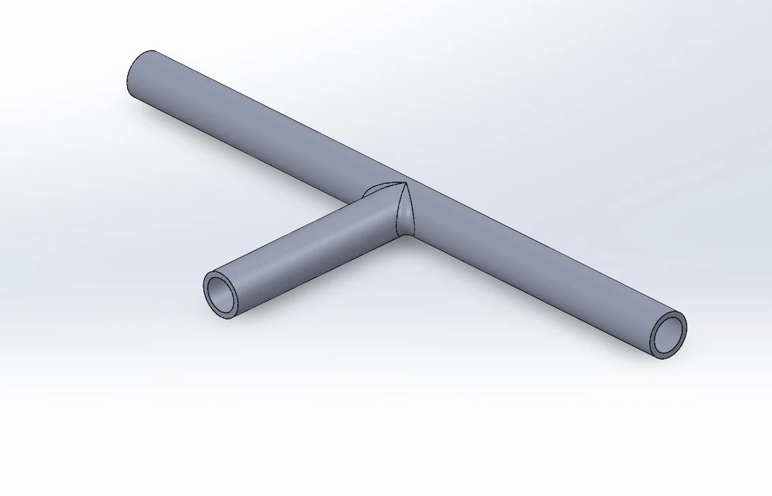
Using a typical household water pipe pressure of approximately 40 kPa, ANSYS Fluent was used to generate the simulation results shown below. There are two inlets, the entrance on the right and the entrance in the middle which is perpendicular pipe to the long straight section, and one outlet on the left
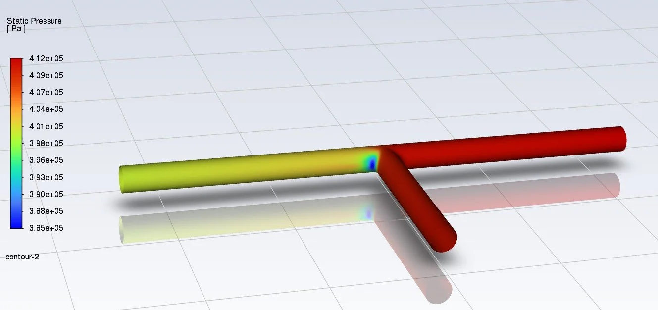
Static Pressure
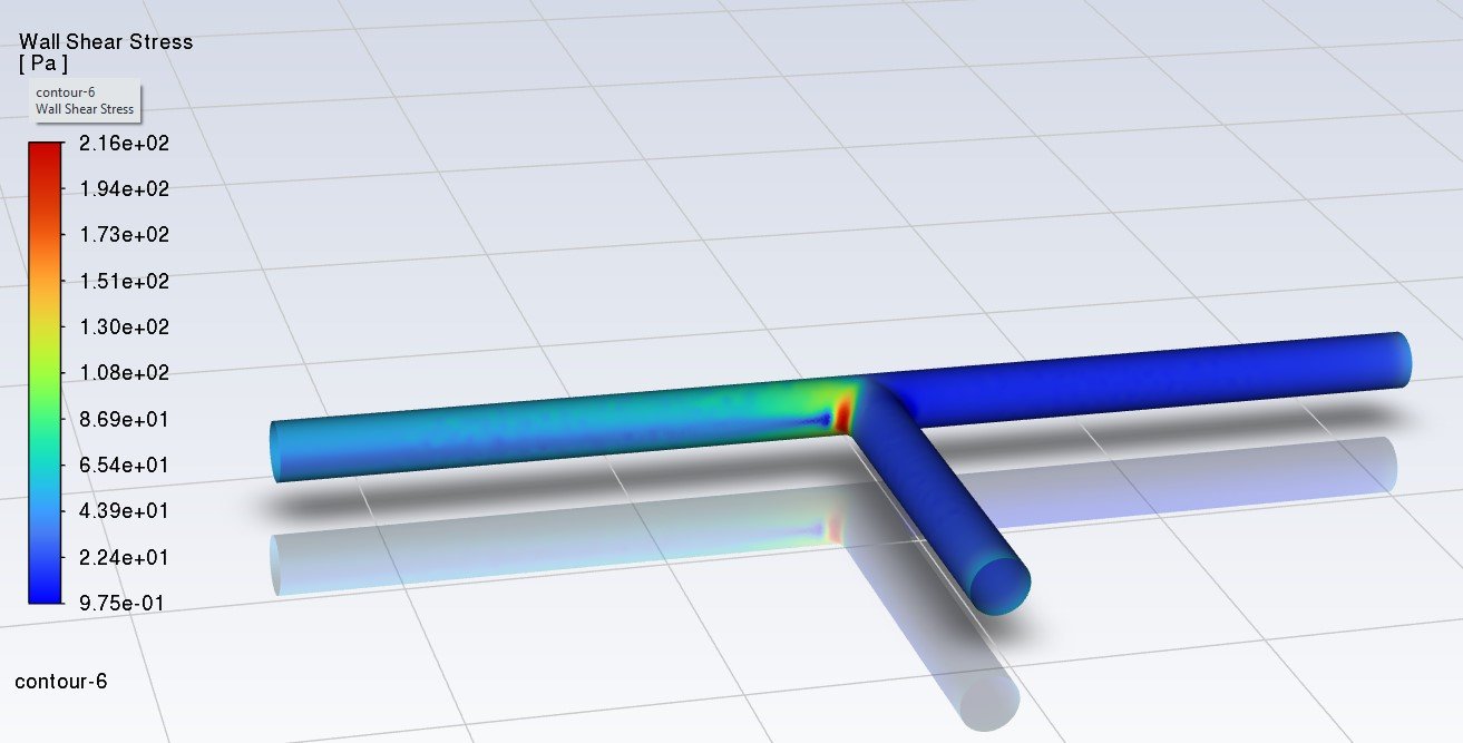
Wall Shear Stress
The static pressure is higher at the two inlets and decreases at the T-joint as the velocity started to increases. The wall shear stress also shows a strong concentration at the fillet on the left corner of the junction.
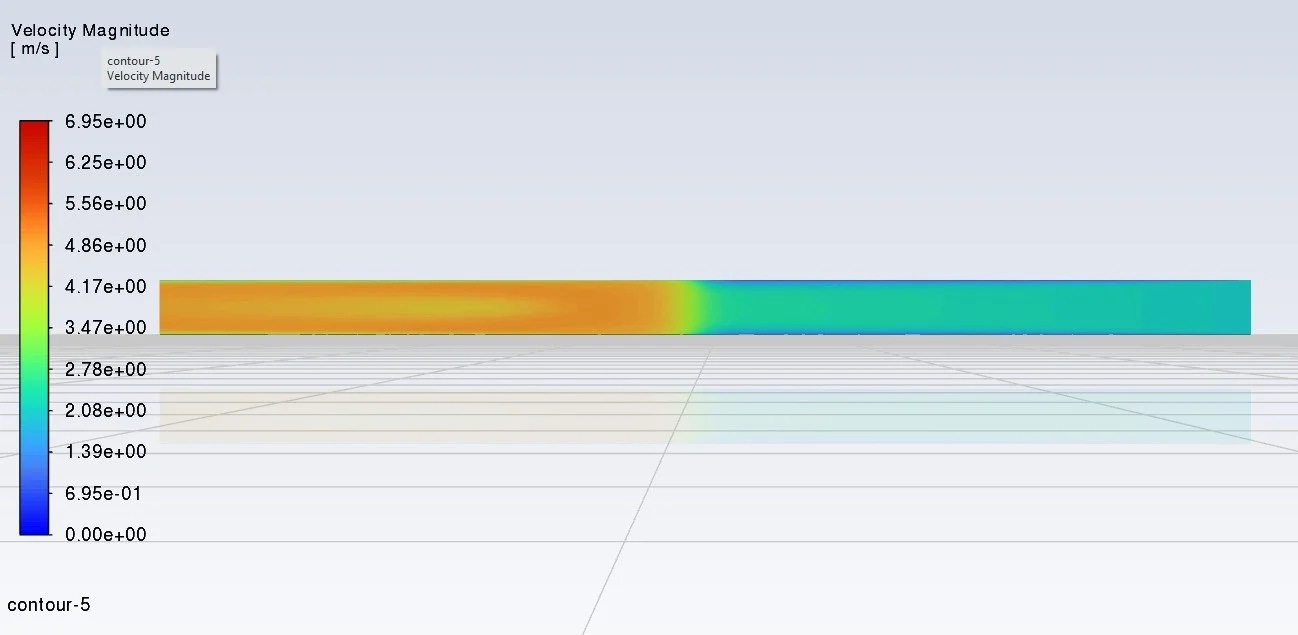
Velocity Magnitude
Upcoming Projects
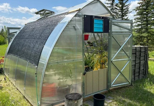
The objective of the Smart Green House project is to maximize growth and yield of crops in agriculture. My team and I will design and implement an automated system that monitors and controls important environment parameters within an enclosed green house, such as temperature, humidity, soil moisture, and light intensity, through a series of sensors and microcontrollers that activate quick responses based on preset commands, and generates reports and alerts of current environment conditions. I will be responsible for designing electrical systems of this project.
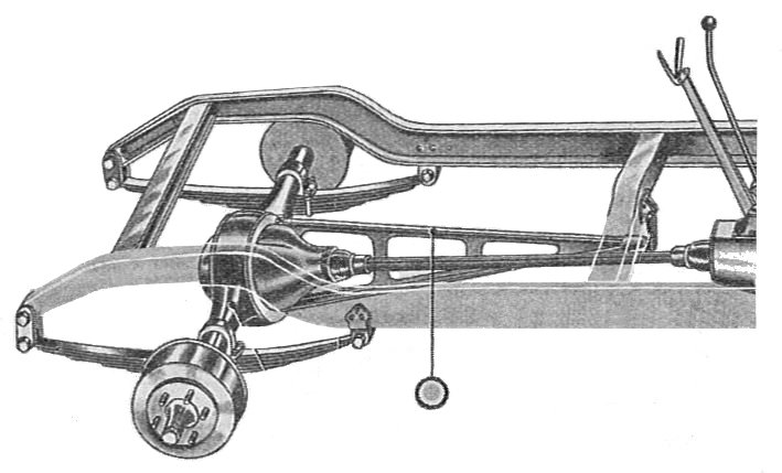
This project involved the CAD development of a 1:10 scale vehicle platform integrating the powertrain, suspension, and steering systems under defined engineering design criteria. I will be the suspension lead and responsible for developing the suspension system layout and geometry to meet the required design criteria, including a front short-long arm (SLA) suspension and rear Hotchkiss suspension with targeted anti-squat characteristics.”
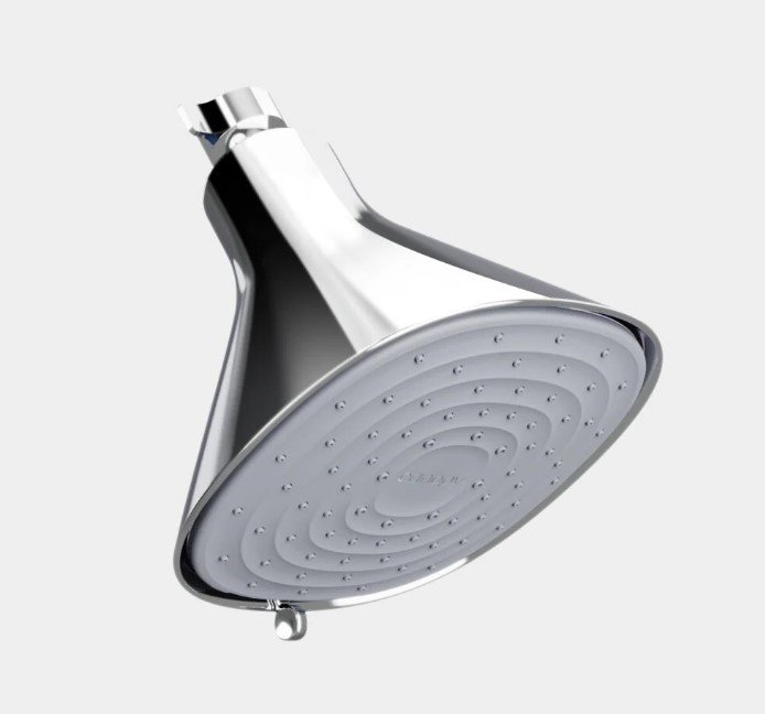
This independent project focuses on designing a custom showerhead for my personal use. The model will be created in SolidWorks and I will use ANSYS Fluent to analyze its flow behavior and spray performance.